3G-SDI Cable Solutions
3G-SDI System Applications
Technological improvements in video systems have made high-definition cameras and displays popular and their integration widespread. 3G-SDI systems are used in aerospace, ground vehicles, shipboards, and surveillance applications, and are important for many people to do their job effectively. These high-definition video systems are often installed in harsh environments with high-temperature variance, intense vibrations, various cable run lengths, and electrical noise. When designing system integration, choosing the proper cable is critical. The main factors to consider when choosing a cable for a 3G-SDI system include:
- Cable loss
- Cable shielding effectiveness
- Ease of termination
- Cable/connector impedance
System Integration Obstacles: Outdated Coaxial Cable Options
3G-SDI systems require higher frequencies to operate, making component engineers’ interconnect cable choices critical for proper system operation. The military spec cable RG179 is frequently used for 3G-SDI systems, but is outdated and was originally designed to serve analog, not digital, applications. RG179’s delicate cable construction results in poor shielding, high loss numbers, and difficult termination, which disrupts system operation and can cause countless hours of troubleshooting and rework.
Solution: Specify PICMates V73263
Rugged cable construction is critical for proper system integration and operation and needs to account for cable path, run length, number of disconnects and environmental electrical noise. In addition, it needs to maintain its geometrical integrity when bent or flexed. PICMates's V73263 cable is a robust solution for 3G-SDI systems and meets PIC’s rigorous manufacturing process and quality controls. Its rugged construction maximizes shielding effectiveness and termination ease, and minimizes cable loss while matching cable and connector impedance. Overall, V73263 makes building, installing, maintaining, and troubleshooting assemblies less time-consuming with its physical properties, electrical characteristics and laser markable jacket.
To demonstrate V73263 is a superior solution to RG179 in 3G-SDI applications, this article will directly compare the two cables against the four main factors commonly considered in cable choice decisions: loss, shielding, ease of termination and cable/connector impedance.
Loss
Per 3G-SDI standards, most receivers require < 20 dB of loss at 1.5 GHz to operate correctly. At 20ft, the loss for RG179 is 6.59dB, while 4.44dB for V73263. The maximum run length of RG179 is about 60’, compared to 85’ with V73263. Lower loss numbers with V73263 allow system integrators more flexibility where the cable is ran and where system components are installed. The greater headroom in shorter lengths also gives the integrator room for minor errors made in termination or installation that may affect the cable’s performance.
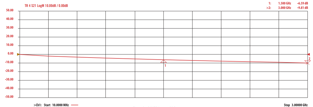
Figure 1a: RG179 Loss at 20 ft
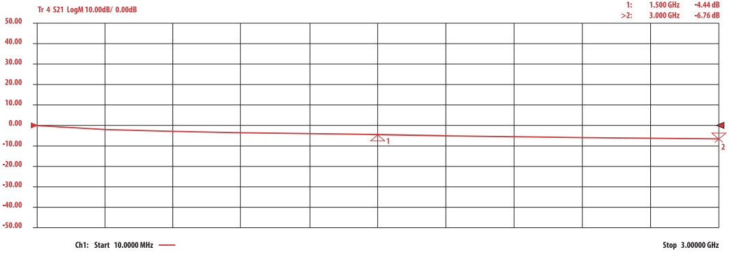
Figure 1b: V73263 Loss at 20 ft
Shielding
Choosing a cable with proper shielding is critical to reducing electrical noise, by containing electrical energy inside the cable and preventing outside signal interference. Poor shielding will result in cable signal disruption and prevent the system from operating correctly. V73263 has a flat, helical strip and a round braid that provides 100% coverage. This construction achieves -110dB of shielding effectiveness. In contrast, RG179 only provides -50dB with 1 round braid.
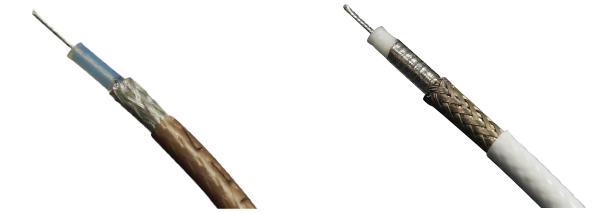
Left: Figure 2a: RG179 cable construction, Right: Figure 2b: V73263 cable construction
Termination
Ease of termination is often an undervalued cable quality until an issue arises. RG179 has a solid dielectric and 30AWG center conductor, which is difficult to cut without compromising the cable’s electrical integrity. V73263 addresses this issue by using a foam dielectric and 26AWG center conductor to simplify the cutting and pinning process. Its center conductor’s tensile strength is almost double that of RG179 at 8.1 lbs compared to 4.4 lbs. V73263 has a foam dielectric that simplifies the termination process by allowing technicians more control over removing the dielectric without cutting the center conductor. In addition, its larger center conductor size provides a larger surface area to terminate the contact.
Connector Impedance
For maximum system effectiveness, the dimensions and impedance of a cable and connector must match. PIC connectors meet or exceed 3G-SDI frequencies of 3GHz, and are offered in a variety of styles for V73263, including ARINC, M39039, and M39012. PIC designs connectors to perfectly match its cables, minimizing the amount of loss or reflections, and ensuring the proper delivery of a signal. For example, since the Mil-Spec size 8 contacts do not have a 75-ohm interface, PIC changed the center pin size to achieve a 75-ohm interface.
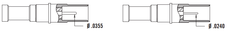
Left: Figure 3a: M39029 Size 8 50 ohm contact, Right: Figure 3b: PIC’s M39029 Size 8 75 ohm contact