Moisture Effects on Coaxial Cable
MOISTURE EFFECTS ON COAXIAL CABLE
MOISTURE: THE ENEMY
There have been reports of TCAS II installations showing signs of RF cable deterioration after only a few years of operation. The cause of these problems has been traced to moisture either in the coaxial cable at the antenna connector or inside the connector itself. Moisture trapped inside a connector can produce effects ranging from unnoticed to serious, depending on the demands of the system. But be assured the cable assembly will be affected if moisture enters. The shields and conductor can suffer corrosion, especially if cleaning is less than meticulous when the connector is applied. However, even if corrosion were not to develop, moisture present in the connector or dielectric can change the characteristic impedance of the cable. Where there is a change in impedance, there is an increase in signal reflection (VSWR). As a result, a sensitive system may become unreliable or, worse, fail.
Before making a blanket indictment of the connectors, cables, cable assembly techniques and/or installation practices, let’s examine the factors that can create this problem.
Moisture can become trapped inside the antenna connector as a result of repeated exposure to significant swings in temperature and atmospheric pressure in the presence of significant relative humidity. (See Figure 1.) In commercial air transport jet aircraft (which account for most TCAS II installations), air temperatures at the skin can cycle from as much as, say, +120°F on a Phoenix ramp to -60°F at 35,000 feet. Pressure may change from about 30 inches of mercury at sea level to about 7 inches (a 75% drop) at 35,000 feet; cabin pressurization, however, can reduce the effect to about a 15% drop.
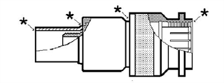
Figure 1. Points of entry for moisture shown for a conventional unsealed TNC connector
Such temperature changes can precipitate moisture in the air, and a drop in cabin pressure can create a partial vacuum in and around the connector. During descent, though the warming of the skin tends to return the moisture to the air, some of it can be drawn into the connector as the pressure returns to higher levels. All this happens differentially; conditions inside the connector will not change as quickly as those around it. Over time, it will equalize again, but there is no way of knowing what “over time” might be.
At the risk of downplaying the advantages of the newer, softer, more porous dielectric materials, it appears these, too, may be implicated in this. Their lower loss, smaller diameter, and lighter weight are important elements in selecting cables for airborne applications, but there is a price to pay. It has to do with the porosity of the dielectric. In effect, the layers of thin Teflon® tape wound around the center conductor resemble a roll of corrugated cardboard. You can picture the spaces for “stuff” to get into. [An exaggerated analogy, of course.]
Solid-dielectric cables go back long before TCAS and might be considered the solution, but it must be noted that they are hardly immune to the effects of moisture and the interior of the connector is still a trap for moisture. A solid dielectric is less absorbent, but the corrosion risks to the conductor and shields are the same. And there are other drawbacks: solid dielectric cables can add pounds to an installation, and will occupy more space because of the larger diameter necessary to meet loss requirements. They are stiffer and will have greater bend radius requirements and so may require other routing considerations in installation. These problems often dictate the choice of the higher-performance construction.
Now, at least theoretically, whatever moisture goes in can also get out. Given the conditions (and freedom) to dry, the problem could be only temporary. Right?
Actually, trapped in the tiny space of a connector, a return to dry-as-the-day-it- was-made is simply impractical — even more unlikely considering the fact that the water in the dielectric isn’t just sitting there waiting to evaporate or be poured out. It may have wicked its way back into the cable by capillary action. Removal by dry heat in a vacuum may be possible, but even if it worked it is (1) tedious, (2) requires special equipment, and (3) calls for undoing and rebuilding the connection at the affected end. All this on top of the R&R of the installed cables in the first place!
So it becomes evident that problem prevention is vital: stop the free flow of moisture into the connector.
ARINC Characteristic 735 doesn’t specifically call for weather-sealed antenna connectors. In fact, when it was adopted, the risks of moisture in advanced, lightweight coax were probably not much of a consideration. (These issues are not mentioned in the Characteristic.)
Weather-sealed connectors are available, but no one knows their long-term ability to block the passage of damaging moisture. However, we do know that weather-sealing helps. The objective here is to prevent moisture from oozing into the space inside the connector where it can get to the exposed end of the cable.
Nothing plastic will seal completely against water molecules in the air, but weather seals will stop the condensed water. A layer of dual-wall (hot-melt glue on the inside) heat-shrink tubing over the cable and fixed end of the weather-sealed connector adds strain relief, but is not adequate moisture protection by itself.
A hermetic seal is the ideal since it blocks the passage of the smallest molecule. It is common in situations such as ceramic-package IC’s, light bulbs, etc. where there must be no chance of the outside atmosphere getting at the sensitive interior. However, a true hermetic seal is accomplished only with the flow of metal to glass or ceramic — obviously a high- temperature operation, but not practical in cables, or most other things for that matter.
PIC’S ROLE
From the beginning, PIC has provided weather-sealed antenna connectors on the coax assemblies we make for TCAS II, TCAS I, Mode S, GPS, SATCOM, MLS, and other RF applications. Also the added protection of dual-wall shrink tube is standard on all PIC cable assemblies. These two measures of sealing provide maximum practical protection against water absorption in coaxial antenna connectors.
The concerns of the commercial aviation industry — especially all TCAS II users — over the effects of moisture in antenna cables are real. Some suggest that correction and prevention of future system problems will get constant attention until there are more answers.
Fact is, connections in all kinds in aircraft are susceptible to environmental contamination. Problem connections include those with the following parameters:
- RF above 100 MHz
- System-defined loss budgets
- Connections at the antenna
- Non-pressurized cabin location
Of these, it is self-evident that there is greater proximity to wide temperature excursions at the antenna. Coupled with moisture in the atmosphere (as opposed to flowing water, which would suggest a leak at or around the antenna) there will be absorption — and not necessarily just a little. One major airframe manufacturer reports that moisture can wick deeply into expanded-tape dielectrics (typical of low-loss coaxial cables) as much as four feet from the connector. (See “In Defense of Low-loss Cable” at the end of this paper.)
While loss effects may be unnoticeable at such a distance, it stands to reason that the longer the span of wet-dielectric cable, the greater the attenuation. This contamination by what could be classified as distilled water (in the air, remember) changes the dielectric constant materially, affecting impedance of the cable. As a result, the VSWR is increased and loss suffers.
Any cable in systems where a minimum loss is specified is at risk, especially those produced with a smaller amount of “leeway” than others, and some systemparameters put a limit on that. See Table 1.
| LOSS LIMITS | ||
|---|---|---|
| MINIMUM | MAXIMUM | |
| TCAS II (per ARINC 735) | 2.0 dB | 3.0 dB |
| TCAS I (Allied Signal) | 2.0 dB | 3.0 dB |
| TCAS I (BFG) | None | 1.5 to 6.0 dB* |
| Mode S (per ARINC 718) | 1.0 dB | 3.0 dB |
| *Requirements Vary | ||
Table 1. List of some of the high/low limits of antenna cable insertion loss for avionic systems. Measurements are specified at 1030 MHz except for BFG TCAS I which is specified
SERIOUS IMPLICATIONS
There have been TCAS and Mode S failures attributable to moisture in the antenna cables. To the extent this is the case the potential consequences are far-reaching.
For one thing, the major role for Mode S transponders is not to make reports to TCAS-equipped neighboring aircraft but to transpond to ATC radar for safe management of the airways. This applies to Mode A and Mode C transponders as well.
Another complication arises in that, while some Mode S transponders are set up to notify the crew of failure, some are not. Dual transponders may be unable to overcome such failure since it occurs in the one common element of the system: the antenna cable.
So something as simple as an unprotected coaxial connection can cause a transponder to go silent without notice. Notwithstanding our confidence in our air traffic control system, it adds to the burden to deal with aircraft which fail to supply helpful, if not vital, data.
REPAIRS
Type C connectors, used on Mode S antennas, are more susceptible to the passage of moisture than TNCs which are used on TCAS antennas. The pressure on the mate gasket is likely at fault; the Type C has a bayonet-like fitting, while TNCs are screwed onto their mating connectors with the potential (and probability) of a tighter fit against the gasket. See Figure 2. Both, however, have been implicated in moisture problems.
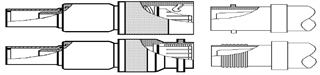
Figure 2. – Type C (top) and TNC mating schemes. Note that the TNC is capable of greater pressure against the sealing gasket due to its threaded mating scheme, as opposed to the Type C which has a spring-loaded bayonet-type connection.
Next, if the pathway for moisture at the cable entry point is unsealed, it may as well be wide open. Some might argue that if it is so open, it will expel moisture-laden air just as readily as it takes it in, leaving the connection in environmental equilibrium. However, there is never complete reversal of such events; an absorbent cable dielectric is always going to be “a little thirsty” when moisture is present. This typifies the principle of capillary action.
If a section of wet cable can be completely dried, which is next to impossible, or removed (How much do you cut off?) it can be re-terminated and deserves to be sealed as thoroughly as possible.
SOME ASSUMPTIONS
The following may make this a little less formidable, but bear in mind they are assumptions.
It might be assumed that the worst of the absorption is in the first few inches of the cable. This length is going to be longer in low-loss cables than in solid-dielectric RG-type cables. Secondly, it might be assumed that cutting and re-terminating the cable with a new, properly sealed connector (not just wrapped in dual-wall shrink-tubing) will solve the problem. However, assurance of restored cable performance comes only with appropriate testing for loss, VSWR, delay, and phase angle (if required).
If the removed length is to more certainly eliminate “all” of the entrapped moisture, it may shorten the cable too much. Add another piece? Not a good idea. Now you start compromising.
Here is one final reason to bite the bullet and replace the cables altogether: with a repaired cable there is still the uncertainty of trapped moisture which can in time enhance the corrosion process and produce yet another mode of failure. Does it buy time? Yes. Does is overcome the problem? Only maybe.
PREVENTION — NOW
Existing installations may or may not be a ticking time-bomb, but so far there is no pattern to suggest that any particular locations or aircraft are less at risk than others.
Nonetheless, taking immediate steps to add protection to mated connectors may at least delay the onset of moisture-caused cable/system failure.
Simply disconnecting the connector from its mate, air-drying both, and re-connecting it with a dual-wall heat shrink sleeve over the entire connection, including several inches of the cable, is truly inadequate. Moisture remaining inside the cable and connector are not only ignored; they become trapped.
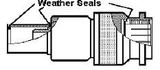
Figure 3. Typical connector weather-proofing. Shows recommended extra protection of dual-wall shrink tube over cable and connector. This covering might also be a wrapped sealant mentioned in the text below, and could cover the entire connection as well.
Actual removal of the connector from the cable and re-termination after drying may produce acceptable results temporarily, but it is a poor second to making a complete cable replacement. Needless to say, replacement connectors should be of weatherproof design. (Figure 3 illustrates typical weatherproofing.)
FINAL ANALYSIS
While there is certainly more experience to be gained, what has been learned so far is :
- Moisture absorption problems are worse in cables with wrapped dielectrics than those with solid dielectrics.
- Moisture absorption is exacerbated by the wide pressure and temperature excursions common to aircraft.
- One effect of moisture is to reduce the dielectric constant, changing impedance, worsening VSWR, and increasing loss.
- Maximum seal potential is realized when using connectors with built-in seals and dual-wall heat shrink tubing or other appropriate sealing method.
For certain, new installations ought to include connectors designed to be inherently weatherproof — at both the cable end and the mating end — with gasketing designed in. The additional surrounding protection should be incorporated at the time of cable assembly , and wrapping the entire mated connection at the time of installation adds yet one more layer of protection.
IN DEFENSE OF LOW-LOSS CABLE
In recent years, advances in manufacturing process for coaxial cable dielectrics have brought us more air — specifically, microscopic spaces incorporated into the Teflon® tape which is wound in an overlapping spiral around the center conductor.
The wound-tape configuration and open air “cells” lead to capillary action, like a sponge in some respects.
While this is, in effect, more apt to draw and trap water molecules, it does result in improvements in cable performance: notably, lower loss, higher velocity of propagation, and lighter weight — to name a few.
These advances far outweigh the risk of moisture contamination, if steps are taken to create a suitable barrier to moisture exposure — or better, if used in a controlled environment.
In aircraft, the environment is almost hostile. Yet the measures covered in this paper can and do reduce the ill effects of moisture on critical parameters.