Like modern avionic instruments which are more sophisticated and sensitive (and capable) than in the past, modern coaxes with softer, lower-loss dielectrics are more easily damaged.
Bending, stretching, and kinks can force the center conductor to one side. This disturbs the common axis of the conductor and shield — they are no longer concentric — and shows up as a change in impedance at the point of “injury.” This can actually be seen on a Time Domain Reflectometer (TDR), an instrument that examines cables for signal reflection, appearing as an electrical “bump” (or dip).
The penalty for mishandling comes in increased losses, reflection quirks and impedance mismatches translating to higher VSWR (Voltage Standing Wave Ratio), and instability of other characteristics. Any of these can have a serious effect on overall system performance.

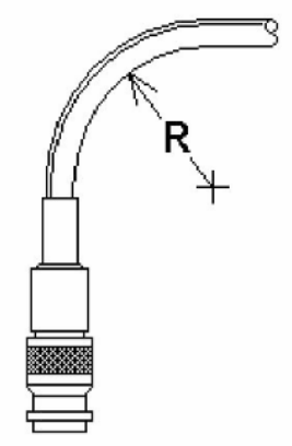
Figure 1: Bend Radius
Bend Radius is relatively easy to visualize (see Figure 1). It is harder to estimate, though, because it is a radius, which by definition is a measurement with an imaginary reference point. Bend Radius can be critical to the installation of coaxial cables — especially where the routing of the cable passes by or through structural elements where an edge may touch the cable. Under any amount of tension, this can make a “corner” in the cable which violates the bend radius limits.
Too often, the damage is invisible, an internal flaw caused by undue forces. Even though the Teflon® jacket on most coaxial cables used on aircraft today is tough and flexible, it can also hide such damage; all the more important to use caution during installation.
To maintain published performance, each cable type has a recommended minimum bend radius. This is usually 5x the outer diameter of the cable, but may be specified as some other figure by the manufacturer. (See Table 1).
A technician needs to remember that physical force, while not always avoidable when making an installation, must be moderate. There are no “cable stretchers” in the tool catalogs.
The most easily damaged part of a cable is the connector. Here the stiffness of the ferrule or clamp which holds the cable to the connector body encounters the flexibility of the cable itself. This is known as a “stress riser,” an edge that concentrates the damaging force on the cable. In some cases, pulling the cable at a right angle to the axis of the connector ferrule can even damage the termination or the connector itself. Where the planned cable routing involves tight bends, it may be better to use a right-angle connector or one of PIC’s new 75° connectors.